


Sonar Viz Bot v1

 7/16/25
Chassis
Chassis & Mounting Layout
- Use a caliper to take measurements
- Chassis:
20.5 cm x 13.0 cm x 5.5 cm
- Chassis:
- Draw Sketch

Measurements
- Chassis:
20.5 cm x 13.0 cm x 5.5 cm
Sketch
CAD (Solidworks)

Tinkercad design (Chloe)


Updated assembly


Caster wheel

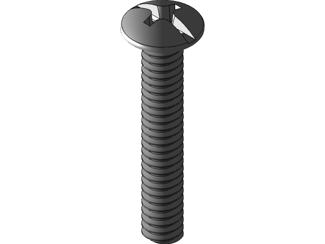
Screws
8-32 x 1-1/4 in. Zinc Plated Combo Truss Head Machine Screw

Part Meaning #8Screw size (diameter) — approximately 0.164 inches (4.17 mm) 32Thread pitch — 32 threads per inch (TPI) 1-1/4 in.Length — the screw is 1.25 inches (31.75 mm) long from head to tip (or from under the head if it’s a flat head)
Caster wheel mounting holes
- Draw construction rectangle for caster’s mounting plate holes

- Draw circles with centers coincident with the rectangle corners
- Clearance hole for screw pass through: 0.17 mm (4.32 in)

- Cut-Extrude

Motor wheel assembly
Gearbox motor

Pass through holes
- Make holes for DC motor shaft

3D Print
Prep
- Go to File → Save As → Choose STL


Caster Wheel mount/adapter
- Draw a 6cm x 6cm square and extrude 2cm

- Extude cut through block

- Change the radius for one hole to 0.3cm to allow ball caster to be screwed on

- Use Insert → Features → Save Bodies to save just the mounting block

Electrical Setup
Arduino Nano BLE
Warning- Arduino Nano 33 BLE operates on 3.3V
- The Nano’s 3.3V output may be enough to for the L298D logic pins, but not the
VCCpins- Never input 5V signals into the Nano BLE
L293D Motor Driver
- Set up L293D Motor Driver circuit
Wiring
| L293D Pin Name | L293D Pin Number | Nano Pin | Function |
|---|---|---|---|
| EN1 | 1 | 11 (ENA) | Right motor speed (PWM) |
| IN1 | 2 | 13 (IN1) | Right motor direction 1 |
| IN2 | 7 | 12 (IN2) | Right motor direction 2 |
| IN3 | 10 | 8 (IN3) | Left motor direction 1 |
| IN4 | 15 | 9 (IN4) | Left motor direction 2 |
| EN2 | 9 | 10 (ENB) | Left motor speed (PWM) |
| GND | 12 | GND | Ground |
Code
L293D_motor_driver_nano.ino
// L293D Motor Driver pins for right motor (Motor A)
const int ENA = 11;    // PWM speed control for right motor
const int IN1 = 13;    // Direction control 1 for right motor
const int IN2 = 12;    // Direction control 2 for right motor

// L293D Motor Driver pins for left motor (Motor B)
const int ENB = 10;    // PWM speed control for left motor
const int IN3 = 8;     // Direction control 1 for left motor
const int IN4 = 9;     // Direction control 2 for left motor

const int switchPin = 7; // Switch to turn robot on/off

int motorSpeed = 0; // Starting motor speed

void setup() {
    pinMode(switchPin, INPUT_PULLUP);

    pinMode(IN1, OUTPUT);
    pinMode(IN2, OUTPUT);
    pinMode(ENA, OUTPUT);

    pinMode(IN3, OUTPUT);
    pinMode(IN4, OUTPUT);
    pinMode(ENB, OUTPUT);

    Serial.begin(9600);
    Serial.println("To infinity and beyond!");
    motorSpeed = 255;
    Serial.print("Motor Speed: ");
    Serial.println(motorSpeed);
}

void loop() {
    motorSpeed = 255;
    // if (digitalRead(switchPin) == LOW) { // Switch ON (pressed)
    if (digitalRead(switchPin) == HIGH) { // Switch OFF
        rightMotor(motorSpeed);
        leftMotor(motorSpeed);
    } else { // Switch OFF
        rightMotor(0);
        leftMotor(0);
    }
}

void rightMotor(int speed) {
    if (speed > 0) {
        digitalWrite(IN1, HIGH);
        digitalWrite(IN2, LOW);
    } else if (speed < 0) {
        digitalWrite(IN1, LOW);
        digitalWrite(IN2, HIGH);
    } else {
        digitalWrite(IN1, LOW);
        digitalWrite(IN2, LOW);
    }
    analogWrite(ENA, abs(speed));
}

void leftMotor(int speed) {
    if (speed > 0) {
        digitalWrite(IN3, HIGH);
        digitalWrite(IN4, LOW);
    } else if (speed < 0) {
        digitalWrite(IN3, LOW);
        digitalWrite(IN4, HIGH);
    } else {
        digitalWrite(IN3, LOW);
        digitalWrite(IN4, LOW);
    }
    analogWrite(ENB, abs(speed));
}
Battery pack
- dimensions: 4” x 2” x 1”
- nominal voltage: 7.7V
- max charge voltage 8.4v
Make Assembly
Wheel
- diameter: 6cm
These are a pair of basic, 65mm wheels with black rubber tires. These wheels are the same ones designed to fit onto DAGUs right angle gear motors utilized in the Magician Chassis and RedBot Kit. With these wheels you will be able to get almost any beginners robot project moving.
Grabcad- 65mm Rubber Wheel.SLDPT
Hobby Gear Motor
Caster wheel
Screws
Assembly

Exploded View
